Tri-Polar
Senior Member

Posts: 134
Likes: 101
|
Post by Tri-Polar on Apr 5, 2021 12:35:19 GMT 10
So my radio died the other day. Few blown caps that i replaced, but the damage was worse than that and beyond my repair ability.
Loved that this took AA, D size and with some creative printing, 18650 cells.
What radio do you guys use that covers the same bands?
|
|
|
|
Post by Joey on Apr 5, 2021 13:25:44 GMT 10
I don't have one currently but have been tossing up getting one for a while now.
Funnily enough, it was pretty much that radio I was looking at from my local Jaycar dealer.
Did it die just from age/use or did it take a few knocks?
|
|
malewithatail
VIP Member
Posts: 3,265 
Likes: 1,301
Location: Northern Rivers NSW
Member is Online
|
Post by malewithatail on Apr 5, 2021 13:49:42 GMT 10
Mate, welcome to the club, I too have repaired several of the same radios, and have one that defies all attempts at getting the display going again. Jaycar wont supply any circuits etc, and their attitude is that you are on yr own. Lets go old school, no computers to screw up. I have several receivers, and you should be able to pick up a Tandy (Realistic) DX series for around $50, and apart from not having FM, it will be as good, if not better (in terms of cross modulation etc) than a newer radio. www.hamuniverse.com/w4jbm/dx160.htmlThere were a series of DX models, DX150, DX160, DX200, getting better with each model. I have a DX 160 with the duel fet front end and it is seriously sensitive. It can pick up anything my WW2 9 valve AR7 can and is on par with the Kenwood TS440 s transceiver (that has a general coverage receiver as well), and you will hear any conversations that are around and above the noise. It doesn't have variable filters etc, but for the price... Lack of a digital display is not an issue as the dial is quite readable, being so long, but a digital display is available, published by Electronics Australia some years ago. I built one for the WW2 Kingsly AR7 and it reads to 1 Kc. Connected to a piece of wire between 10 and 100 meters long and it will literally receive the world at your fingertips. It also runs from 12 v dc, drawing about 500 ma max, so operation from a small solar system is feasible. Kenwood also brought out a series of receivers at the same time, but having used some of them, the Tandy one eats them all. The other thing I like about it, is that it looks like a receiver, a big dial, knobs, not switches, and a nicely backlit dial using bulbs, giving a ambiance that is lost with leds. And it has a reasonable audio stage as well, quite capable of filling a house with music from the local am stations. After 40 odd years, calibration may be a bit out, but the manuals and adjustments are all easy to access and with a signal generator, you can put it back to factory specs in a few minutes. In fact, a full instrument alignment, even when they were new, made them even better as the factory alignment was a bit hit and miss. All components used are standard, off the shelf types, no special IC's, but some had a IC audio stage, but once again, it was a standard Toshiba 1 watt audio ic, so they are easy and cheap to repair. Dial stringing is a bit fiddly, but the manual has a exploded diagram that shows how it works, and its tedious to do, but not hard. By now, you will probably have to give the pots a squirt of CRC to get rid of the scratch noise, but they are easily accessible. Like I said earlier, apart from the lack of FM, they were a solid receiver that we longed for in our youth and can hold their own with most receivers of today. If at first you don't succeed, destroy all the evidence of your trying. |
|
malewithatail
VIP Member
Posts: 3,265
Likes: 1,301
Location: Northern Rivers NSW
Member is Online
|
Post by malewithatail on Apr 5, 2021 13:50:49 GMT 10
I certainly cant recommend the Jaycar radio.
If at first you don't succeed, destroy all the evidence of your trying.
|
|
Tri-Polar
Senior Member
Posts: 134
Likes: 101
|
Post by Tri-Polar on Apr 5, 2021 13:53:14 GMT 10
Not too sure to be honest. It was looking like new, but it had been kicked around, possible wet at some times.
My uneducated guess was it was the LCD/button system that failed in the end.
Pretty devastated as now thats ANOTHER thing that i have to replace.
|
|
malewithatail
VIP Member
Posts: 3,265
Likes: 1,301
Location: Northern Rivers NSW
Member is Online
|
Post by malewithatail on Apr 5, 2021 13:58:16 GMT 10
The micro seems to have some issues with corrupted bits in its e prom. Not good for a radio that you may be relying on to get intel during a crisis.
Pm me for more info re radio comms.
If all you have is a hammer, the whole world looks like a nail.
|
|
malewithatail
VIP Member
Posts: 3,265
Likes: 1,301
Location: Northern Rivers NSW
Member is Online
|
Post by malewithatail on Apr 5, 2021 20:40:30 GMT 10
The other alternative , is to build your own. Keep away from anything to do with a micro, its not easy to repair after the fall without specialized parts. I have made many radios, but the best one is a 3 valve , regenerative detector and runs a speaker with enough audio to fill the room with sound. It is obviously not as easy to use as a commercial one, but is reasonably sensitive, is emp/cme proof and almost infinitely repairable. It runs from 12 v dc, drawing about 1 amp, and has a rf stage for better noise performance. It uses easy to get tv type valves, 2 6CB6's, (pentodes), and a 6GW8 triode/pentode audio type. One 6CB6 is the rf stage, the other is a regenerative detetcor9wth a little super regeneration as well), and the triode is the audio pre amp, the pentode part is the output stage. The power supply is a DC to DC converter, based on a couple of easily obtainable 2N3055 transistors and a small Jaycar 12 volt center tapped power transformer. Its frequency coverage is changed by the use of 3 small plug in coils. Obviously, its not as sensitive as a commercial set, but has those other advantages. Transistor designs are also available and my bug out radio is a homemade 3 transistor, 1 IC (the audio output) type that is also a regenerative design.
As I've discussed before, don't overlook the crystal set for a bug out radio. no battery's needed, only a piece of wire for an aerial and its not traceable as it doesn't radiate any signals, unlike all modern radios do. Pm me for details of the circuits.
Success always occurs in private, failure in full view.
|
|
|
|
Post by Joey on Apr 5, 2021 21:30:24 GMT 10
Sounds like you need to do a thread on your homemade radio with lots of pretty pictures  |
|
malewithatail
VIP Member
Posts: 3,265
Likes: 1,301
Location: Northern Rivers NSW
Member is Online
|
Post by malewithatail on Apr 6, 2021 15:34:49 GMT 10
Will try....
|
|
Tri-Polar
Senior Member
Posts: 134
Likes: 101
|
Post by Tri-Polar on Apr 6, 2021 19:32:05 GMT 10
|
|
malewithatail
VIP Member
Posts: 3,265
Likes: 1,301
Location: Northern Rivers NSW
Member is Online
|
Post by malewithatail on Apr 6, 2021 20:05:38 GMT 10
Seems to have all the options. Computer control, strictly I suppose its microprocessor control, whilst giving lots of features, leaves you vulnerable to sudden failure, either from emp/cme, or static discharge etc. Older non micro controlled radios seem to be more reliable, especially if you consider that it may be the only means of gathering intel after the collapse, it has to be reliable. Also, micro controlled radios are quite often, battery pigs, I have a Sony ICF2001and it will chew a set of D size battery's in 10 hours. Rechargeable battery's are always an option. As a portable set, it looks OK though.
If you can find your way around a radio, you should be able to build your own.
By the way, I've taken a closer look at the Jaycar radio I have and its tuning seems to be analogue, the micro only does the display, clock etc. I've got the audio stage functioning now, there is a small surface mount transistor that switches the audio stage to standby, and it was kaput. Bridging this out, (Pins 1 and 12 of the IC to battery positive) brought that stage back to life. Tomorrow I hope to come to grips with why the display only shows the clock and wont scan etc. I am beginning to suspect a broken track around the band switch, or even the switch itself, as there is evidence of someone else having a go at it.
Quality assurance doesn't.
|
|
|
|
Post by milspec on Apr 6, 2021 22:08:30 GMT 10
As I read this post my Digitech radio is sitting on the table next to me. Haven't had any technical issues with it yet, except that I seem to inadvertently put it in locked mode frequently and then can never reliably get the bloody thing unlocked without a reset. Honest to God it shouldn't take having to read a bloody manual to figure that out. / exit mini rant.
On the plus side, the D cells last for ages.
|
|
malewithatail
VIP Member
Posts: 3,265
Likes: 1,301
Location: Northern Rivers NSW
Member is Online
|
Post by malewithatail on Apr 7, 2021 9:50:45 GMT 10
The issue with the lock mode is probably another crook surface mount transistor, they seems to be of poor quality and suffer from internal leakage paths, resulting in the external voltage not able to overcome the internal leakage current, and causing the device to stay switched on.
Now have the display displaying a shortwave frequency, not just the clock, but its not responding to changing the frequency, nor is there any audio from the speaker yet. The audio stage is responding to a signal being fed into the line in socket, so we are making progress. Lack of circuits isn't helping though.
I hope to post some pictures and circuits of some of my homemade radios soon.
The answer is a definite maybe.
|
|
malewithatail
VIP Member
Posts: 3,265
Likes: 1,301
Location: Northern Rivers NSW
Member is Online
|
Post by malewithatail on Apr 7, 2021 16:03:07 GMT 10
Some information for those who have a kaput Jaycar Digitek AR1748 radio. Finally found all the faults and got it fired up, still have a hour or two's work to reassemble it into its case. Here is what I found and the fixes. Start with the audio stage, that's the board with the pots on it for volume etc. Check that the audio IC, a CD8227GP, has battery voltage (9 volts) between pins 4 (Ground or negative) and pins 12 and 1 (positive 9volts). If there is only power, called VDD, on pin 12, then the IC isn't being switched to full power from sleep mode, either the mute is on, or as in my case, the small surface mounted transistor that switches power between pin 12 to pin 1 was faulty. As I have no need for the mute function, I just removed the transistor by grabbing it with a pair of long nosed pliers and pulled it from the board. I soldered a small link from pin 12 to pin 1 and the audio stage was working. Now to the main radio board, the one with the wave change switches mounted on it. Check on the white connector from the audio board that 9 volts is on the end pin, labelled ext.., and 3 volts in on the next pin along, labelled power. Then you will need to remove the screws holding the wave change switches on next, and check the phased locked loop IC, a LC72137 has ground or negative on pin 15, and plus 3 volts dc on pin 14. This 3 volts is also fed to the IF amplifier chip, a TA8132. This chip should have 3 volts positive on pin 5, and negative or ground on pin 12. In my case, these voltages were missing. Further tracing came to a surface mounted transistor on the middle of the board, and there was 3 volts on its emitter, but nothing on the underside of the board. It seems to be a 9 volts to 3 volts linear regulator. Further close investigation revealed a plated through connection that had a funny look to it. Sure enough, it was open circuit and a small wire bridge across the board and the radio burst to life, as the volume was fully on. A closer look at the area of the fault showed some brown substance, probably some sort of glue to hold things in place. Removing this revealed a bit of green corrosion under it, so look for brown gunk in your radio and remove it, and check for corrosion underneath. There was clear evidence of someone else having been there before as a lot of connections had been resoldered in a rough way. I've now cleaned up the board and just have to reassemble it. The radio seems to be quite a reasonable design, and uses quality IC's, such as Toshiba, and Sharp, but, the lack of cooperation from Jaycar with service information means I cant recommend it for prepping use, as if it fails, its not easy to repair. By the way, in my comments re short wave radios, I forgot to mention another good one, its a Barlow Wadley XCR30 and was made by Barlows TV company in South Africa in the 1970's. Its a solid performer, and is phase locked loop, but with discrete transistors, lots of them, all standard BC series available for cents anywhere. The analogue dial is calibrated to be able to readout the frequency tuned to within 500 hz or better, and being crystal locked will stay in tune almost for ever. Servicing information is freely available and it gives remarkable results just on its pull out whip aerial. Battery life from 6 D cells is very good. Broadcast band reception is Ok, but there have been mods published to improve that. Short wave performance is great, and it can also handle SSB, with proper filters for each side band. Its in a metal and die cast box, so quite heavy, but robust. I took mine to South Australia on the bus and it never missed a beat. I've had one faulty transistor, which was a BC108 and replaced for 20 cents. About 20,000 were made and I've had mine for nearly 30 years. Its a radio that doesn't look to pretentious, in fact, it looks like a portable radio, but this one covers all the short wave bands, as well as SSB for hams etc. The only design fault is that there is a heterodyne, or whistle, each megacycle due to the internal 1 Mhz crystal oscillator. Its annoying, but only affects reception on even Megacycles, and can be turned around carefully. There was a model that had the standard FM band on it as well. Brief specs. The Barlow Wadley covers 0.5 to 31 MHz in 1MHz bands. The set is a triple conversion super heterodyne with intermediate frequencies of 42.5, 2-3 and 0.455 kHz. It uses a Wadley loop to cancel the drift from the first local oscillator, so that the set only drifts off frequency by the amount the second local oscillator drifts. (The second mixer is fed from the product of the first oscillator and amplified 1MHz crystal harmonics). The first two mixer stages use a balanced diode mixer, presumably to assist strong signal handling and reduce spurious responses. An RF preselector is used ahead of the first mixer. In effect, this has three wavebands: 0-2, 2-7 and 7-30 Mhz. An arrangement of cams and microswitches is used, so that only a single "Antenna Tuning" knob is used. The set has a product detector for SSB, and the selectivity is selected according to mode. The nominal bandwidth is 3kHz for SSB and 6kHz for AM. The filters have appreciable skirt selectivity, so the AM does not sound muffled. 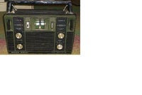  If it doesn't fit, force it. If it breaks it needed replacing anyway. Attachments:
|
|
malewithatail
VIP Member
Posts: 3,265
Likes: 1,301
Location: Northern Rivers NSW
Member is Online
|
Post by malewithatail on Apr 7, 2021 19:56:14 GMT 10
Update on the Jaycar radio.
Got it all back together, found a set of battery's and switched on. FM works OK, all the usual stations, the broadcast band likewise, not outstanding sensitivity, but adequate, short waves 1 and 2... deaf as a post. When connected to my 160 meter full wave Zepp aerial, some short wave signals are audible, but almost nothing using the built in rod aerial. Tomorrow looks like another dive into the innards to determine the next issues. At least I'm now dealing with the analogue sections and no microprocessors involved. Also, when switching from AM to SW1, the switch needs to be wiggled, otherwise it tunes to the FM band. Oh well, its all good clean fun !
I forced it, it didn't break, so I got a bigger hammer.
|
|
malewithatail
VIP Member
Posts: 3,265
Likes: 1,301
Location: Northern Rivers NSW
Member is Online
|
Post by malewithatail on Apr 11, 2021 8:27:13 GMT 10
Update on the Jaycar radio. Seems the issue with the low sensitivity on the upper short wave bands was due to dry joints on the wave change switch as well as a faulty internal/external antenna switch. Once they were repaired, it seems to work, still have to put it all together to finally test it but....
Another issue has reared its head, that is some of the buttons on the control panel aren't working. I cant switch the radio on except with the sleep timer switch, as well the fast scan and clock set buttons don't work. Luckily its a single sided board so should be easy to trace tracks to the fault. I suspect its a dry joint as there are a host of 0 ohm surface mount resistors on it and they all seem to be to do with the push buttons and jumping over other tracks. Its not a very good design from an engineering standpoint as there are a lot of crossovers, which u normally try to avoid in designing a PCB.
Will post updates as I get time.
He who hesitates is probably right.
|
|
malewithatail
VIP Member
Posts: 3,265
Likes: 1,301
Location: Northern Rivers NSW
Member is Online
|
Post by malewithatail on Apr 17, 2021 17:04:51 GMT 10
Update, this morning I finally had time to have a look at the Jaycar radio. Tried tracing through the push buttons, but the tracks go everywhere on the board and my eyes are not that good any more. It would seem that the buttons have a duel function, one is to switch the timer for the led backlights, the other is the function that you want. Anyway, I gave up tracing PCB tracks and resorted to the solder everything in sight fix. It seemed to work and the buttons are all working. I even soldered the micro and the surface mount components, so there was a dry joint somewhere.
I still couldn't recommend the radio as a preppers radio due to the abysmal service from Jaycar and the reliability of what is still a current model radio. For alternatives, see the post on preppers radios, under communications.
Virus detected - delete hard disk ?(Y)
|
|
malewithatail
VIP Member
Posts: 3,265
Likes: 1,301
Location: Northern Rivers NSW
Member is Online
|
Post by malewithatail on Apr 18, 2021 20:06:05 GMT 10
Its fixed...for now anyway. Put the Jaycar radio back into its case and, zilch, no sound. Pulled it apart again and found a broken wire to the speaker from the pcb. Redid both ends of the wire and put it all back together.....Weak, distorted sound. Pulled it apart again, found the switch terminals inside the headphone socket were intermittent high resistance. Bridged it out as I wont be using phones anyway. Put it all back together and ....it works. It passed the 2CH test well enough, and both WWV and WWVH were audible at good strength on 5, 10 and 15 megs. Tuned around the 9 meg tropical band and heard the usual suspects of religious broadcasters.
Going to give it to a bloke I know brother who is into prepping as he hasn't got a short wave radio.
Don't follow me, I'm lost.
|
|
spatial
Senior Member
Posts: 2,191
Likes: 1,507
Member is Online
|
Post by spatial on Apr 18, 2021 22:10:31 GMT 10
|
|
mwat
New member
Posts: 2
Likes: 0
|
Post by mwat on Apr 19, 2021 17:16:27 GMT 10
I have found that all the hand cranked radios I've seen/used have plastic gears. Some don't seem to be particularly form stable and warp over time. It's called dimensional stability. It's not that hard to make your own hand rank generator of much better quality than any brought one.
U start off with an old permanent magnet motor some kind, an old 3 phase DC motorfrom a dead electronic drill will work. Attach some form.of handle to it and turn away. A super capacitor will store enough energy for a radio or led light. It's not hard to rig up a falling weight of rocks or bricks to use gravity as the energy source. In fact some commercial products came out that did the same thing. I seem to remember the plastic gears stripped easily.
Such a device is on the list to make,after I make the gasifier unit.
Gravity is a myth, the Earth sucks.
|
|


